ATtiny Running Lisp
24th September 2019
This project describes how to run programs in the high-level language Lisp on a Microchip ATtiny 3216 microcontroller costing just over a dollar:
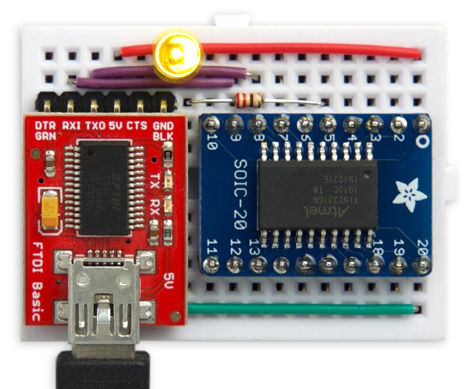
Blinking an LED using uLisp running on a $1 ATtiny3216.
It uses my Lisp interpreter for microcontrollers, uLisp.
ATtiny uLisp – Specification
Memory available: 306 Lisp objects (1224 bytes).
EEPROM: 64 Lisp objects (256 bytes).
Language: uLisp, a subset of Common Lisp, with over 150 Lisp functions and special forms. For a full definition see uLisp Language Reference.
Types supported: list, symbol, integer, stream, character, and string.
An integer is a sequence of digits, optionally prefixed with "+" or "-". Integers can be between -32768 and 32767. You can enter numbers in hexadecimal, octal, or binary with the notations #x2A, #o52, or #b101010, all of which represent 42.
User-defined symbol names can have up to three characters consisting of a-z and 0-9. Any sequence that isn't an integer can be used as a symbol; so, for example, 12a is a valid symbol.
There is one namespace for functions and variables; in other words, you cannot use the same name for a function and a variable.
Includes a mark and sweep garbage collector. Garbage collection takes under 1 msec.
Interfaces:- 11 10-bit analogue inputs using analogread: 0 to 5, 8 to 9, and 14 to 16.
- Eight 8-bit analogue outputs using analogwrite: 0, 1, 7 to 11, and 16.
- One 8-bit DAC output using analogwrite on 2. Set the DAC Voltage Reference from the Tools menu.
- 17 digital inputs and outputs using pinmode, digitalread, and digitalwrite: 0 to 16.
- I2C using with-i2c and restart-i2c: 8 (SDA) and 9 (SCL).
- SPI using with-spi: 14 (MOSI), 15 (MISO), and 16 (SCK).
The numbers refer to the Arduino pin numbers. For numbers 0 to 13 these are the package pin number minus 2; for numbers 14 to 16 these are the package pin number minus 3.
Arduino pin 3 is connected to an LED.
Introduction
Previously the smallest microcontroller that would run my uLisp interpreter was the ATmega328P, the basis for the popular Arduino Uno. This provides 32Kbytes of flash memory, 2Kbytes of RAM, and a 16MHz processor.
When I saw the specifications of Microchip's new ATtiny 0-series and 1-series ranges of microcontrollers I realised that it might be possible to run uLisp on the ATtiny3216 and ATtiny3217, which have 32Kbytes of flash and 2Kbytes of RAM, making these the lowest cost processors capable of running Lisp; see Getting Started with the New ATtiny Chips.
For this project I chose the ATtiny3216 which has 20 pins in an SOIC package, and so is relatively easy to solder onto a breakout board. You could also use the ATtiny3217, which has 24 pins in a QFN package, but you would need surface-mount skills.
The circuit
Here's the circuit:
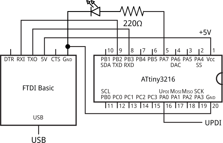
Circuit of the ATtiny3216 running uLisp.
You need a USB-to-serial converter to allow you to use the Arduino IDE's Serial Terminal to enter Lisp programs via a USB cable. There are several alternatives available; I used the FTDI Basic Breakout from Sparkfun [1], available from HobbyTronics in the UK [2].
For details of the ATtiny3216 pinouts see Spence Konde's megaTinyCore page: megaTinyCore/ATtiny_x16.
Using uLisp
With uLisp running on an ATtiny3216 you can upload programs directly from the Arduino IDE Serial Monitor. Just type or copy-and paste the program into the field at the top of the Serial Monitor window, and click the Send button or press Return.
You can control the I/O ports directly, access I2C and SPI peripherals, and write programs to automate functions. You can also save small programs to EEPROM so they are retained when the power is disconnected, and they can be configured to run automatically on restart.
If you're not familiar with Lisp, think of it as a scripting language with a very consistent syntax: everything is written as a list of items, in brackets. For example, the commands to define pin 3 as an output and turn on the LED connected to that pin are just:
(pinmode 3 t)
(digitalwrite 3 t)
where t (true) means on. The command name is always the first item in a list, so to add two numbers you write:
(+ 123 456)
Although putting the operator "+" first might look unnatural, it means that operators and functions are handled in a consistent way, and allows you to express many operations more concisely. For example, you can sum five numbers by writing:
(+ 12 34 56 78 90)
For more information and a simple introduction to Lisp see the tutorials at www.ulisp.com.
Examples
Here are a few simple examples of using uLisp on the ATtiny3216:
Blink
The above circuit has an LED connected to the Arduino pin 3 which you can flash with the following Blink program, blk:
(defun blk (&optional x)
  (pinmode 3 t)
  (digitalwrite 3 x)
  (delay 1000)
  (blk (not x)))
Run it by typing:
(blk)
Exit from the program by entering ~.
For a more interesting variant of Blink that flashes the sequence of prime numbers see Blinking primes.
Saving your programs
You can save your currently defined programs to EEPROM with the command:
(save-image)
You can then load them after disconnecting and reconnecting the power with:
(load-image)
Note that the ATtiny3216 has only 256 bytes of EEPROM so you will be limited in how much you can save.
Playing a tune
You can use the uLisp note function to play musical notes on any pin. For example, connect a piezo speaker between PA5 (Arduino pin 1) and GND and define the following function sca (scale):
(defun sca (pin)
  (mapc
   (lambda (n) (note pin n 4) (delay 500))
   '(0 2 4 5 7 9 11 12))
  (note))
Then to play a scale on the speaker give the command:
(sca 1)
Analogue inputs
The ATtiny3216 provides 11 10-bit analogue inputs that you can read using the uLisp function analogread.
For example, the following program continuously reads analogue input 0 (PA4) and displays its values in the Serial Terminal:
(defun adc ()
  (loop
   (print (analogread 0))))
Run it by typing:
(adc)
As before, exit from the program by entering ~.
You can also display the value graphically by choosing Serial Plotter from the Arduino IDE's Tools menu; here's a 1Hz sine wave:
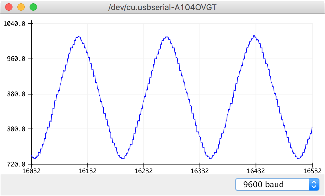
Analogue input displayed in the Arduino IDE's Serial Plotter.
Analogue outputs
The ATtiny3216 allows you to generate eight 8-bit analogue outputs with PWM, using the uLisp function analogwrite. For an example of using the PWM analogue outputs see Mood light.
In addition, the ATtiny3216 includes an 8-bit DAC output, which gives a steady analogue voltage on PA6 (Arduino pin 2). This can be varied between 0V and the DAC Voltage Reference; for example, if you set this to 4.30V when you upload uLisp, the following function allows you to set the DAC output to a specific voltage, in mV:
(defun dac (mv)
  (if (> 0 mv 4300) (print "Out of range")
    (analogwrite 2 (/ (* mv 5) 84))))
For example, to set the voltage to 2.5V give the command:
(dac 2500)
The scale factor 5/84 was chosen as a very close approximation to 256/4300.
You could also write a program to slowly sweep the output from 0 to 4.3V.
Interfacing using I2C
uLisp makes it simple to interface to I2C peripherals. First, here's a simple port scanner that prints out the address of any I2C peripherals on the SDA and SCL pins:
(defun scn ()
  (dotimes (p 127)
    (with-i2c (str p)
      (when str (print p)))))
Run this by typing:
(scn)
Here's an example of the ATtiny3216 controlling an I2C LED 8x8 dot-matrix display:
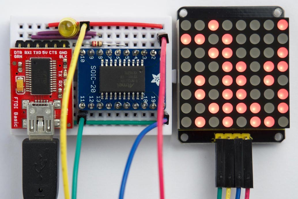
uLisp on an ATtiny3216 controlling an I2C LED 8x8 dot-matrix display.
For details see LED 8x8 dot-matrix display.
More examples
For more examples of using uLisp see the uLisp site. Most of the Simple examples will run on the ATtiny3216 uLisp.
Uploading uLisp
First download the latest AVR version of uLisp from the Download uLisp page.
Compile the program using Spence Konde's megaTiny Core on GitHub. Choose the ATtiny3216/1616/1606/816/806/416/406 option under the megaTinyCore heading on the Board menu. Check that the subsequent options are set as follows (ignore any other options):
Chip: "ATtiny3216"
Clock Speed: "20MHz"
DAC Voltage Reference: "4.30V"
Programmer: "jtag2updi (megaTinyCore)"
Then upload the program to the ATtiny3216 using a UPDI programmer. You can make a UPDI programmer from an Arduino Uno, or other ATmega328P-based board, as described in Make UPDI Programmer.
You can ignore the error "Cannot locate flash and boot memories in description".
You should then be able to connect the USB cable to the USB-to-Serial board, select it from the Port menu, and enter commands at the Serial Monitor as described in Using uLisp above.
For help with using uLisp visit the uLisp Forum.
- ^ FTDI Basic Breakout on Sparkfun.
- ^ FTDI Basic Breakout on HobbyTronics.
blog comments powered by Disqus