Morse Code Message Pendant
14th February 2022
This is a pendant that transmits a secret message in morse code by flashing an LED:
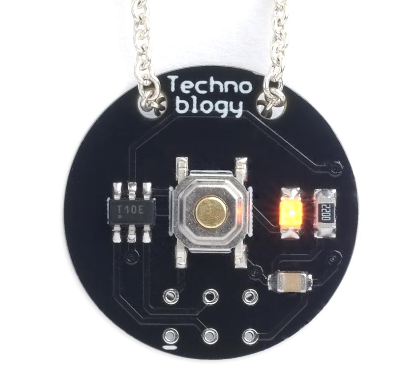
Morse Code Message Pendant based on an ATtiny10.
When you press the button the pendant flashes the message in morse code on the LED. You could use it it deliver a Valentine's Day message to a special person, send secret information, or simply as a conversation piece.
The pendant is powered by a 3V coin cell on the back. Press the push button to start the pendant displaying the message, and press it again to turn it off. Alternatively, the pendant turns off automatically after flashing the message.
Introduction
I got the idea for this while I was developing an earlier project, AM Morse-Code Transmitter. It occurred to me that morse code is a perfect protocol for sending a text message with a minimal interface. You could make the message even more secret by using an infra-red LED, in which case it will only be visible on a mobile phone camera.
This circuit uses an ATtiny10, which has only six pins, and has only 1024 bytes of flash program memory and 32 bytes of RAM, but even so the Morse code Message Pendant is capable of storing a message of over 100 words.
A push button connected to the reset pin turns the light display on or off, and the ATtiny10 stays in sleep mode when the display is off. The current consumption in sleep mode is under 0.1µA, which will give negligible battery consumption when the pendant isn't being used.
Morse code
Morse code uses a series of short and long flashes to encode the letters A to Z, the digits 0 to 9, and a few punctuation marks, so that messages can be sent by sound or light between two people who know the code. To keep messages as short as possible the most common letters in English have a short encoding, with the longer encodings used for less common letters:
The morse code sequences for the letters and digits.
The circuit
Here's the circuit of the Morse Code Message Pendant:
Circuit of the Morse Code Message Pendant, based on an ATtiny10.
I used an ATtiny10 in an SOT-23 package. They seem to be sold out in all the suppliers in the UK or USA at the moment, but they're still available from AliExpress; see the Parts list. The LEDs, resistors, and capacitor are all 0805 size. The LED can be any colour, but red, yellow, or orange will give the longest battery life because they have a lower forward voltage of 2.2V or less.
The button is the same as I've used on several of my projects, a miniature SMD push button available from Sparkfun [1], or Proto-PIC in the UK [2].
The pendant is designed to work with a 3V 12mm coin cell type CR1225; you could also use types CR1216 or CR1220. The cell fits in an SMD 12mm coin cell holder [3].
► Parts list
Construction
It should be possible to solder all the components by hand, using a fine-tipped soldering iron, but I used a Youyue 858D+ hot air gun set to 250°C. Once all the SMD components were soldered on the front of the board I finally soldered the coin cell holder onto the back of the board using a conventional soldering iron:
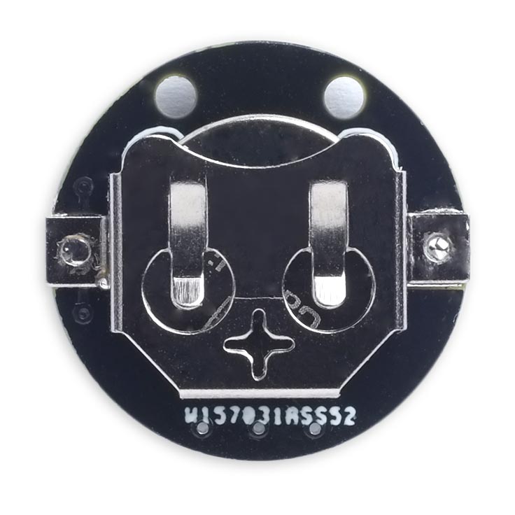
Back of the Morse Code Message Pendant, showing the coin cell holder.
This pendant is similar to my earlier project ATtiny10 POV Pendant. However, with that project it was difficult to upload a program because the five connections you needed to connect to were at different positions on the board. In the Morse Code Message Pendant I've brought the programming connections to a standard 2x3 pin pad that you can connect to with a set of six pogo pins. I'll give details of how to make a suitable Pogo probe below.
The program
Timing
The timing of morse code is based on the duration of a dot, which is one unit:
| Feature | Timing |
| Dot | 1 unit |
| Dash | 3 units |
| Gap between dots or dashes | 1 unit |
| Gap between characters | 3 units |
| Gap between words | 7 units |
A typical speed for beginners uses a dot duration of about 200 msec.
I experimented with using the watchdog timer to generate an interrupt to do the timing, or the Timer/Counter0 to generate an interrupt to do the timing, and these both worked fine. However, in the end I decided that it was simpler to use Timer/Counter0 to measure the intervals using polling.
First, in setup(), the 16-bit Timer/Counter0 is set up in CTC mode, which counts up from 0 until the counter matches the value in Output Compare Register A, with a prescaler of 1024:
  // Set up Timer/Counter for 1 msec per count
  TCCR0A = 0<<WGM00;                       // CTC mode
  TCCR0B = 1<<WGM02 | 5<<CS00;             // CTC mode, / 1024
With a prescaler of 1024 the 1MHz clock frequency is divided down to about 1msec per counter unit.
To time an interval we call Wait(), which delays for n dot units, where Dot has the value 200:
void Wait (unsigned int n) {
  GTCCR = 1<<TSM | 1<<PSR;                // Keep the counter reset
  OCR0A = Dot * n;                        // Define compare value
  TIFR0 = 1<<OCF0A;                       // Clear flag
  GTCCR = 0;                              // Start counter
  while ((TIFR0 & 1<<OCF0A) == 0);        // Wait for compare match
}
This stops the counter, writes the interval into the Output Compare register OCR0A, starts the counter, and then waits until the compare flag is set.
To reduce the speed of the morse code increase the value of Dot.
Morse code generation
The message to be generated is stored in the string Message[]:
const char PROGMEM Message[] = "You're the one I want to share my life with. ";
As there's so little RAM it's important to specify the PROGMEM directive to ensure that the message is stored in flash program memory. Note, however, that you don't use the pgm_read_byte() function to access the program memory as on other ATtiny and ATmega processors.
The program uses a look-up table Chars[] of codes giving the sequence of dots and dashes for the letters A to Z, the digits 0 to 9, and a selection of punctuation marks. Again, this is stored in program memory:
const uint8_t PROGMEM Chars[48] = {
//A           B           C           D           E           F
  0b01100000, 0b10001000, 0b10101000, 0b10010000, 0b01000000, 0b00101000,
//G           H           I           J           K           L
  0b11010000, 0b00001000, 0b00100000, 0b01111000, 0b10110000, 0b01001000,
//M           N           O           P           Q           R
  0b11100000, 0b10100000, 0b11110000, 0b01101000, 0b11011000, 0b01010000,
//S           T           U           V           W           X
  0b00010000, 0b11000000, 0b00110000, 0b00011000, 0b01110000, 0b10011000,
//Y           Z           0           1           2           3
  0b10111000, 0b11001000, 0b11111100, 0b01111100, 0b00111100, 0b00011100,
//4           5           6           7           8           9
  0b00001100, 0b00000100, 0b10000100, 0b11000100, 0b11100100, 0b11110100,
//+           ,           -           .           /           ?
  0b01010110, 0b11001110, 0b10000110, 0b01010110, 0b10010100, 0b00110010,
//&           '           (           )           !           "
  0b10101110, 0b01000100, 0b10110100, 0b10110110, 0b10101110, 0b01001010,
};
Each eight-bit code consists of a '0' for a dot and a '1' for a dash, followed by a final additional '1' to indicate the end of the sequence, and then padded with zeros to eight bits.
The routine Letter() takes an ASCII character, converts it to the correct index in the look-up table Chars[], and then outputs it as a sequence of dots and dashes by calling DotDash():
void Letter (char letter) {
  uint8_t index;
  letter = letter | 0x20;                 // Convert letters to lower case
  if (letter == ' ') { Wait(4); return; }
  else if (letter >= 'a' && letter <= 'z') index = letter - 'a';
  else if (letter >= '0' && letter <= '9') index = letter - '0' + 26;
  else if (letter >= '+' && letter <= '/') index = letter - '+' + 36;
  else if (letter == '?') index = 41;
  else if (letter >= '&' && letter <= ')') index = letter - '&' + 42;
  else if (letter >= '!' && letter <= '"') index = letter - '!' + 46;
  else return;
  uint8_t code = Chars[index];
  while (code != 0x80) {
    DotDash(code & 0x80);
    code = code<<1;
  }
  Wait(2);
}
Here's the routine DotDash():
void DotDash (bool dash) {
  PORTB = PORTB | 1<<LED;                 // LED on
  if (dash) Wait(3); else Wait(1);
  PORTB = PORTB & ~(1<<LED);              // LED off
  Wait(1);
}
DotDash() adds a gap of one unit after each dot or dash, so Letter() takes this into account when defining the gap between characters and words.
On/off button
The push button resets the ATtiny10, and each time the program runs it toggles the state of the variable Power:
Power = ~Power & 1;
Power is defined as .noinit, which means that it doesn't get initialised to zero when the program runs:
uint8_t Power __attribute__ ((section (".noinit")));
So it allows the push button to act as an on/off switch for the circuit.
The main program
When Power is true the main program outputs the message:
void loop () {
  int p = 0;
  while (Power) {
    char c = Message[p++];
    if (c == 0) break;
    Letter(c);
  }
  PORTB = 0;                               // Turn off LED
  sleep_enable();
  sleep_cpu();
}
At the end of the message the program puts the ATtiny10 into sleep mode.
Programming the ATtiny10
Unlike the SPI protocol used to program the older AVR chips, such as the ATmega328 in the Arduino Uno, or the UPDI protocol used by the latest AVR chips, such as the AVR128DA28, the ATtiny10 uses a programming protocol called TPI (Tiny Programming Interface) which needs five wires. Fortunately Thomas Fischl's excellent USBasp programmer supports this protocol [4]; They are widely available on eBay [5].
Connecting the USBasp
Connect the USBasp to the ATtiny10 as shown in the following diagram:
Connecting the USBasp programmer to an ATtiny10.
Making a pogo-pin programmer
If you get a USBasp programmer with a 10-pin to 6-pin adapter for ISP programming you can replace the 6-pin socket with a set of six pogo pins [6] for programming the Morse Code Message Pendant, as follows:
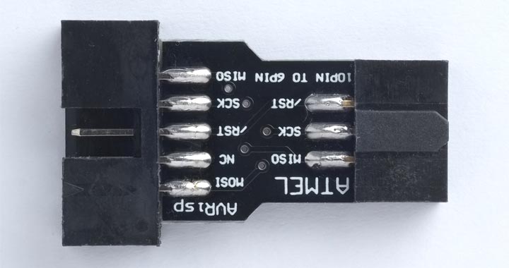
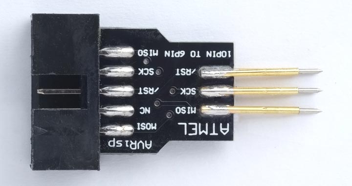
- Unplug the 10-pin to 6-pin adapter from the USBasp ribbon cable.
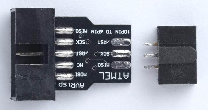
- Unsolder the 6-pin header socket from the adapter.
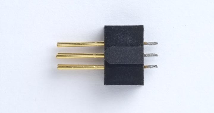
- Push the pogo pins into the header socket, point side first, to use the socket to hold the pins in the correct alignment.
- Solder the six pogo pins to the 10-pin to 6-pin adapter board, three on each side, and then remove the header socket.
You can then plug the ribbon cable back into the adapter board, and use the pogo pins to connect to the six pads on the PCB.
Uploading the program
Here are the instructions for programming the ATtiny10.
- Install the ATtiny10Core by following the instructions on my GitHub repository ATtiny10Core.
This should add an ATtiny10Core heading to the Board menu.
- Choose Board from the Tools menu, and select the ATtiny10/9/5/4 option under the ATtiny10Core heading; it's the only option.
- Choose ATtiny10 from the Chip menu.
- Choose USBasp from the Programmer option on the Tools menu.
- If you have inserted a battery in the Morse Code Message Pendant board, remove it before programming.
- Press the USBasp pogo pins to make contact with the six pads on the pendant PCB, aligning the GND terminal with the pad marked with a white bar.
- Choose Upload to upload the program.
Resources
Here's the Morse Code Message Pendant program: Morse Code Message Pendant Program.
Or get the program from GitHub, together with the Eagle files for the PCB so you can make yourself a board: https://github.com/technoblogy/morse-pendant.
Or order boards from OSH Park here: Morse Code Message Pendant.
Or order boards from PCBWay here: Morse Code Message Pendant.
- ^ Mini Push Button Switch - SMD on SparkFun.
- ^ Mini Push Button Switch (SMD) on Proto-PIC.
- ^ Coin Cell Battery Holder - 12mm (SMD) on Farnell.
- ^ USBasp - USP programmer for Atmel AVE controllers on www.fischl.de.
- ^ USBASP Programmer Cable & Adapter on eBay.
- ^ Pogo pins "Needle Head" (10 pack) on Adafruit.
blog comments powered by Disqus