Simple LCD Character Display
15th September 2018
LCD character displays are a convenient low-cost way to provide readable text output for a project. This project shows a simple way to interface a 16x2 character display to an ATmega328 on a prototyping board with the minimum of wiring:
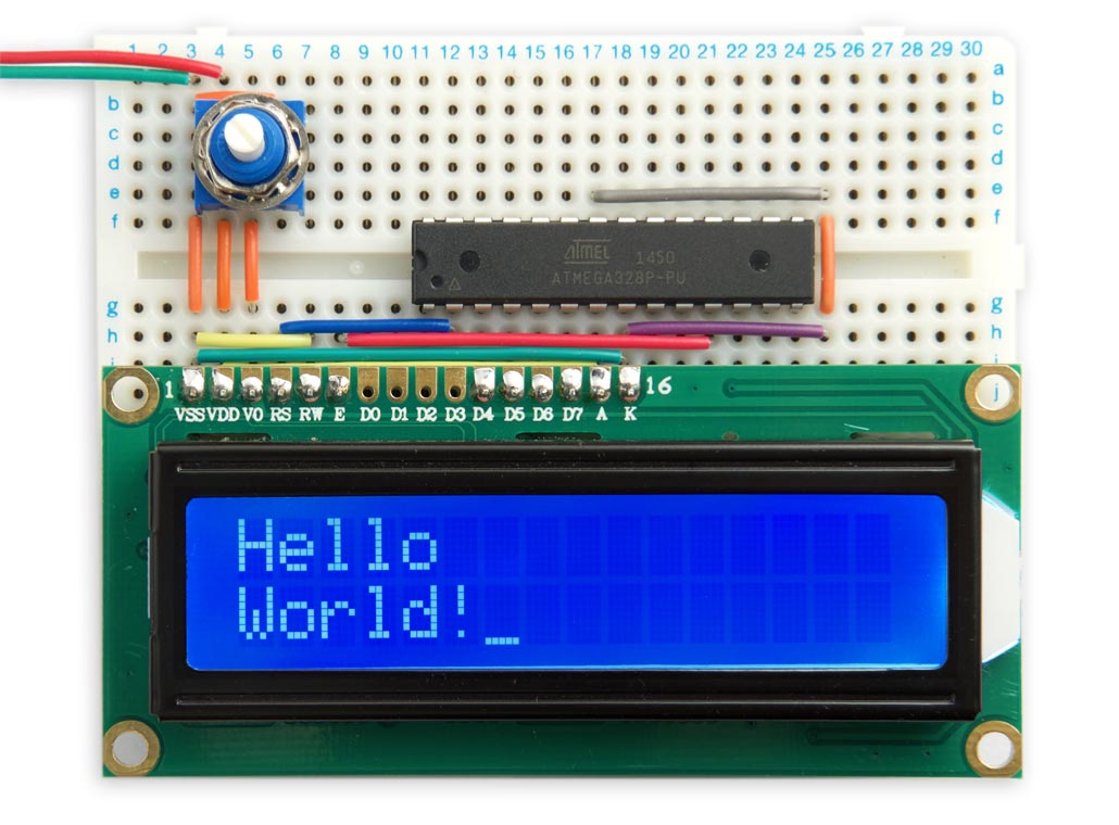
Simple LCD character display, interfaced to an ATmega328.
Introduction
LCD character displays are typically based on the Hitachi HD44780 display driver [1], and are available in a variety of colours and formats, including 16 characters x 2 lines, 20 characters x 4 lines, 16 characters x 4 lines, and 8 characters x 2 lines. The displays usually include an analogue contrast adjustment signal, and an LED backlight.
The following example is based on a 5V 16x2 LCD display [2] [3] but should work with other displays. Alternatively if you need more advanced features, or have a different type of display, there's an Arduino Liquid Crystal library.
The displays include a built-in ASCII character set, so the interface program is relatively simple. The displays offer two interface modes: 8-bit, or 4-bit. This application uses the 4-bit mode which saves I/O lines by sending the data in two 4-bit parts, using just D4 to D7.
I first tested this program in uLisp, my Lisp for the Arduino, before converting it into C; see LCD character display.
The circuit
You need to connect six I/O lines from the Arduino to the display; four for the data lines D4 to D7, and two for the enable and RS lines. This application keeps the wiring and program simpler by using four consecutive pins in one ATmega328 register for these four data pins. By aligning the display with the ATmega328 on the prototyping board we save having to connect these wires:
Circuit of the LCD character display interface.
The pins you've used should be specified by these constants:
const int data = 1;    // PD1 to PD4 connect to D4 to D7 on the display
const int enable = 5;  // PD5
const int rs = 0;      // PD0
Tip: Don't fit pin headers to the pins D0 to D3 on the display module; these aren't used, and leaving them unconnected may allow you to save some wiring between the Arduino board and the display module, as in my prototype in the photograph above.
Defining the LCD class
First we define a class called LCD based on the Print class. This enables it to inherit the behaviour of the standard I/O functions such as print() to print strings and integers:
class LCD : public Print {
  public:
    void init();
    void cmd(uint8_t);
    size_t write(uint8_t);
  private:
    void nib(uint8_t);
};
Initialising the display
First the routine init() defines all the pins used by the display as outputs, and sends four commands to initialise the display:
void LCD::init () {
  DDRD = DDRD | 0xF<<data | 1<<enable | 1<<rs;   // Make data E and RS pins outputs
  PORTD = PORTD & ~(1<<rs);                      // Take RS low
  cmd(0x33);                                     // Ensures display is in 8-bit mode
  cmd(0x32);                                     // Puts display in 4-bit mode
  cmd(0x0e);                                     // Display and cursor on
  cmd(0x01);                                     // Clear display
}
The commands are:
- 0x33 and 0x32 put the display into 4-bit mode.
- 0x0e turns the display and cursor on. Change this to 0x0c if you don't want a cursor.
- 0x01 clears the display.
The first two commands are designed to work whether the display is initially in 8-bit or 4-bit mode, as follows.
If the display is initially in 8-bit mode, as it is after power-on, the first byte 0x33 is interpreted as two commands:
0b0011xxxx, 0b0011xxxx
where xxxx are the 'don't care' states of the lower-four data lines, D0 to D3. These leave the display in 8-bit mode.
If, however, the display is initially in 4-bit mode, as it would be if you just reset the Arduino, the first byte 0x33 is interpreted as a single command:
0b00110011
which puts the display into 8-bit mode. In either case the second byte 0x32 is interpreted in 8-bit mode as the two commands:
0b0011xxxx, 0b0010xxxx
which put the display into 4-bit mode.
Sending data
The routine nib() sends a four-bit nibble to the four data pins, and pulses the enable pin:
void LCD::nib (uint8_t n) {
  PORTD = (PORTD & ~(0xF<<data)) | n<<data | 1<<enable; // Send data and enable high
  PORTD = PORTD & ~(1<<enable);                  // Take enable low
  delay(1);                                      // Allow data to execute on display
}
The routine write() calls nib twice to send a byte:
size_t LCD::write (uint8_t b) {
  nib(b>>4); nib(b&0xf);
  return 1;
}
Finally, the routine cmd() calls write() to send a command. The RS line is taken low for commands:
void LCD::cmd (uint8_t c) {
  PORTD = PORTD & ~(1<<rs);                      // Take RS low
  write(c);
  PORTD = PORTD | 1<<rs;                         // Take RS high
  delay(1);                                      // Allow to execute on display
}
Demo program
First create an instance of the LCD class, called lcd:
LCD lcd;
Then to setup the display, and write Hello World! on the two lines of the display run:
void setup() {
  lcd.init();
  lcd.print("Hello");
  lcd.cmd(0xc0);                                 // Cursor to start of second line
  lcd.print("World!");
}
Some useful commands are:
- 0x01 clears the display.
- 0x80 moves the cursor to the start of the first line.
- 0xc0 moves the cursor to the start of the second line.
- 0x0c turns off the cursor.
- 0x0e turns on the cursor.
Compiling the program
Compile the program with my ATmegaBreadboard hardware configuration on GitHub, following the instructions there to add it to your Arduino hardware folder: ATmegaBreadboard.
Select the ATmega328 option under the ATmegaBreadboard heading on the Boards menu. Then choose ATmega328P, 8 MHz (internal), and B.O.D Disabled from the subsequent menus. Choose the correct programmer from the Programmer option on the Tools menu; for example, USBtinyISP if you're using the Sparkfun Tiny AVR Programmer. Choose Burn Bootloader to set the fuses appropriately; then choose Upload to upload the program.
Here's the whole program: Simple LCD Character Display Program
- ^ HD44780 datasheet on Sparkfun.
- ^ 16x2 LCD Display White/Blue LED Backlight on HobbyTronics.
- ^ Standard LCD 16x2 + extras - white on blue on Adafruit.
blog comments powered by Disqus