Light Lab
14th January 2026
Light Lab allows you to experiment with different patterns on RGB LED NeoPixel (WS2812 or WS2812B) or DotStar (APA102 or SK9822) strips. It has a display that lets you choose one of several different patterns from a menu, and provides three interactive controls to allow you to vary the parameters of each pattern:
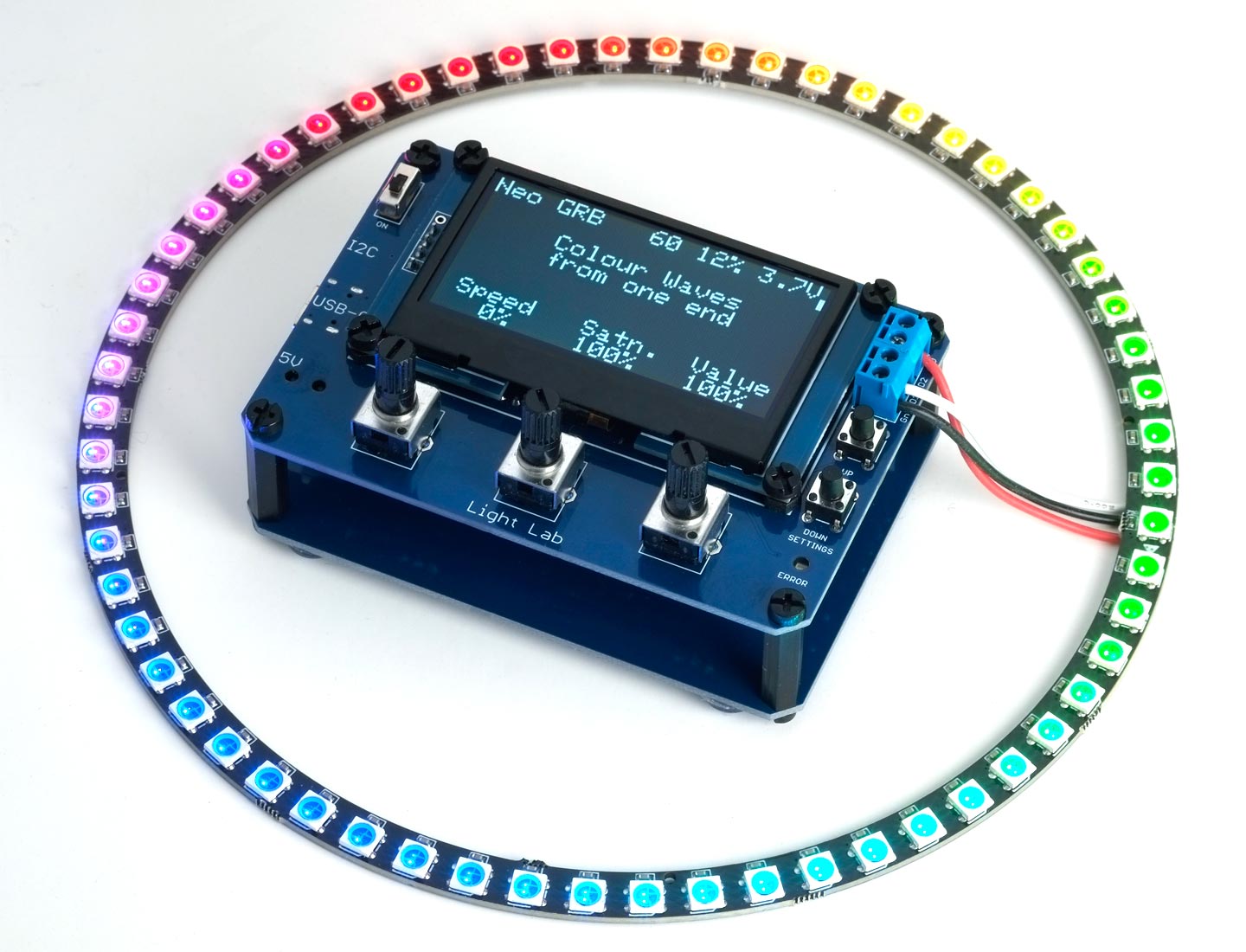
Light Lab lets you drive NeoPixel or DotStar strips with attractive customisable light patterns.
There are 22 different built-in patterns catering for LED strips, rings, and matrices, and you can easily add your own. Most of the patterns use fractional calculations to provide smooth gradations of colour and brightness.
Light Lab can be powered from USB-C, a 5V power jack, or an internal protected 18650 Lithium cell. It supports NeoPixel (WS2812 or WS2812B) or DotStar (APA102 or SK9822) LED displays with up to 160 RGB LEDs.
Introduction
I've recently been experimenting with driving NeoPixel displays using the peripherals in DA, DB, and DD series AVR microprocessors, and this set me to thinking about what would an ideal platform for designing and experimenting with NeoPixel displays.
The idea was to create something like my sound synthesiser, Sound Lab - a Simple Analogue Synthesiser, but for coloured RGB LEDs. This led to Light Lab, which has the following features:
- A controller that will drive a strip, ring, or matrix of NeoPixel (WS2812 or WS2812B) or DotStar (APA102 or SK9822) LED displays.
- Three potentiometers that allow you to interactively vary three parameters of each pattern.
- A large 2.42" 128x64 OLED display that displays information about each pattern, and labels the three potentiometers with legends and the current settings.
- Up and down buttons that allow you to step between the alternative patterns.
- An on/off switch, to turn on or off Light Lab.
- Three alternative power options: USB-C, a 5V power jack, or a protected 18650 Lithium cell.
- A STEMMA QT I2C connector, to allow you connect an I2C sensor (for future expansion).
It's based on an AVR128DB28 processor, in conjunction with a CP2102N USB-to-Serial converter to allow you to upload new firmware via the USB-C port.
Using Light Lab
Once you've built Light Lab and uploaded the program as described later in the article, here's how you use it.
Connecting an LED strip
The first step is to connect a NeoPixel (WS2812 or WS2812B) or DotStar (APA102 or SK9822) LED display to the screw terminals at the right of the board. It can be a strip, circle, or any other configuration.
- Connect the GND wire (usually black) to the GND terminal, and the 5V wire (usually red) to the +5V terminal.
- If you're connecting a NeoPixel strip, connect the DI (Data In) wire (often green) to the D1 terminal. The D2 terminal is unused:
![]()
Connecting a NeoPixel LED strip.
- If you're connecting a DotStar strip, connect the CI (Clock In) wire (often yellow) to the D1 terminal, and the DI (Data In) wire (often green) to the D2 terminal:

Connecting a DotStar LED strip.
Switching on for the first time
When you first use Light Lab:
- Switch on while pressing the DOWN button to display the Settings screen:
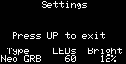
You can then specify the settings you want to use:
- Turn the Type control to specify the type of LEDs you are using, DotStar, Neo GRB (NeoPixels with GRB pixel order; most common), or Neo RGB (NeoPixels with RGB pixel order).
- Turn the LEDs control to specify the number of NeoPixels or DotStars connected to Light Lab.
There is a choice of the most common options, from 30 to 160 LEDs.
- Turn the Bright control to specify the maximum brightness; this can be one of the values 6%, 12%, 25%, 50%, or Max (100%).
- Press the UP button to exit from Settings.
The settings are remembered even when power is disconnected from Light Lab.
You can change the settings at any time by holding the DOWN button when switching on.
Note that if you accidentally select the wrong LED type or number of LEDs you may get an incorrect display, but it won't cause any harm to the Light Lab or LEDs.
The main screen
The main screen shows the settings, current pattern, and the function and value of each of the controls:
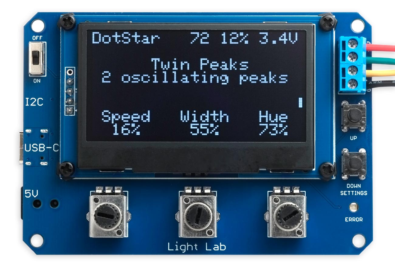
The Light Lab screen showing the settings, current pattern, and control functions and values.
The top line shows the settings (LED type, number of LEDs, and global brightness), and the voltage at the LED output. When powered by the USB port the voltage will be about 0.2V below the expected 5V because of the Schottky diode protecting the output. When powered by a lithium battery the voltage will be between 4.2V and 3.2V as the battery is depleted.
The centre lines show the name of the pattern, and a description.
The bottom two lines show the function of each control, and the current settings. Depending on the pattern the Speed control may go from 0% to 100% or from -50% to 50%. The other settings go from 0% to 100%.
On the right-hand side of the screen is a scroll bar showing your current position in the list of patterns.
Selecting a pattern
- Press the UP or DOWN button to step between the available patterns.
Adjusting the pattern
- Turn each of the controls to achieve the effect you want.
Blanking the display
If you don't want the light from the display to interfere with the effect of your RGB LEDs you can blank it as follows:
- Press the UP and DOWN buttons together.
To turn it back on press the UP and DOWN buttons together again, or select a different pattern.
Other LED displays
Although this article talks about LED strips, Light Lab can be used with RGB displays arranged in other layouts. Here are a couple of examples:
- NeoPixel Rings: A range of NeoPixel rings in different sizes are available from Adafruit and AliExpress. For example, 12 RGB NeoPixels [1], 16 RGB NeoPixels [2], 24 RGB NeoPixels [3], and 60 RGB NeoPixels [4].
Of the moving patterns the following are ideal for use with rings as they join up seamlessly: Colour Waves, Twin Peaks, Theatre Lights, Theatre Lights 2, and Rainbow Bands.
- NeoPixel Matrices: These are square arrays of NeoPixel displays interconnected into a single strip. For example, 8x8 RGB NeoPixels [5] [6] and 8x8 RGB DotStars [7].
The Matrix Circles and Matrix Message patterns are specifically designed for an 8x8 matrix.
Built-in patterns
Light Lab includes the following 22 patterns:
Static RGB Display
Allows you to adjust the Red, Green, and Blue components of the colour, or turn them all to maximum to get white. You can use this pattern to explore how the three colours red, green, and blue combine. For example, make yellow with 100% Red and 100% Green, orange with 100% Red and 50% Green, cyan with 100% Green and Blue, magenta with 100% Red and 100% Blue, and white with 100% Red, 100% Green, and 100% Blue.
Static HSV Display
Allows you to adjust the Hue control to change the colour, the Satn. control to change the saturation, and the Value control to change the brightness. You can use this pattern to explore how the HSV colour model works. For example, see how the hue cycles through all the colours from red at 0%, yellow at 17%, green at 33%, cyan at 50%, blue at 66%, magenta at 83%, and back to red at 100%. Also, see how reducing the Satn. dilutes the colour with white, and reducing Value reduces the brightness.
Colour Waves
This displays a hue spectrum along the LED strip. The spectrum animates, giving the appearance of moving along the strip. You can adjust the Speed, Satn., and Value.
Colour Circles
This displays a hue spectrum spreading out from the centre of the LED strip. The spectrum animates, giving the appearance of moving outwards or inwards. You can adjust the Speed, Satn., and Value.
Circular Bands
This displays bands of a single colour spreading out from the centre of the LED strip. The bands animate, giving the appearance of moving outwards or inwards. You can adjust the Speed, Hue, and Satn..
Cylon
Displays a peak of coloured LEDs moving back and forwards along the strip. You can adjust the Speed, Width of the peak, and Hue.
Twin Peaks
Displays two peaks of coloured LEDs rotating around the strip. You can adjust the Speed, and the hue of each peak, Hue1 and Hue2.
Pendulums
Displays six coloured peaks, two of each of three colours, that bounce backwards and forwards along the strip like pendulums. You can vary the Speed, and the width of each of set of three, Width1 and Width2.
Theatre Lights
Every third LED lights up, moving along the strip. You can adjust the Speed, Hue, and Satn..
Theatre Lights 2
All the LEDs light up in a sequence of three colours, moving along the strip. You can adjust the Speed, Hue, and Satn..
Coloured Bands
Displays coloured bands moving smoothly along the strip that change colour every few seconds. You can adjust the Speed, number of Bands, and Hue.
Rainbow Bands
Displays bands of rainbows moving along the strip. You can adjust the Speed, number of Bands, and Hue.
Fireworks
Displays three coloured peaks that appear suddenly, and then fade away before the next one appears. You can adjust the Speed, Hue, and Satn..
Sparkling Lights
Displays sparkling coloured lights. You can adjust the Speed of sparkling, the Delay before they go out, and the Satn..
Twinkling Lights
Displays twinkling white lights against a coloured background. You can adjust the Speed of twinkling, and the Hue and Value of the background. Set the background to pale blue to create a night sky effect.
Beating Peaks
Red, blue, and green peaks pulse up and down, and you can vary the rate of each one with the Speed1, Speed2, and Speed3 controls to get interesting interactions as they overlap.
Computer Display
Displays bands of flashing white lights like on the front panel of an early mainframe computer. You can adjust the Speed, number of Bands, and Value.
Snakes
Displays random multicolour snakes travelling along the strip. You can adjust the Speed, Hue, and Satn..
Fireflies
Multicolour fireflies fly around at random along the strip. You can adjust the Speed, Hue, and Satn..
Snowstorm
The LED display gradually fills up with random coloured lights until it's completely full, and then it starts again. You can adjust the Speed, Hue, and Satn..
Matrix Circles
Displays moving coloured circles on an 8x8 RGB LED matrix. The circles animate, giving the appearance of moving outwards or inwards. You can adjust the Speed, Satn., and Value.
Matrix Message
Displays a scrolling message on an 8x8 RGB LED matrix. You can adjust the scrolling speed with the Speed control, and each letter is displayed in a different colour which you can adjust with the Colours and Satn. controls. The demo message is "Happy Birthday Zoe!" but you can enter any message in the string message[] in the program. Note that this pattern won't make much sense on an LED strip or ring!
Timings
To refresh a strip of NeoPixels each bit takes 1250ns, making 30µs per RGB NeoPixel, or about 1ms for a strip of 30 LEDs. To animate NeoPixels without flicker we need to refresh them about 50 times a second, or at least once every 20ms. This hardware NeoPixel Driver uses only about 10% of the processor time to update the strip, leaving 90% to calculate the next pattern frame. The DotStar driver is even faster.
The limiting factor is the time taken to evaluate the pattern for each update of the LED strip. Using the space-time expression approach used here we evaluate a single function for every colour channel of every LED in the strip. For my first prototype I used floating-point functions, and these took about 1ms per RGB LED. To update the strip every 20ms this would limit the length of the strip to 20 LEDs.
For this final version of Light Lab I converted the functions to fixed-point arithmetic, and on the AVR microcontroller I'm using this turned out to be a factor of 9 faster than the floating-point versions. This allows you to drive strips of up to 180 LEDs, which is ample as it's greater than the limit imposed by the 3A USB power available from Light Lab.
Powering Light Lab
To allow as much flexibility as possible I've incorporated three alternative powering options in Light Lab:
USB-C
USB-C is capable of providing 3A at 5V, and this will often be the preferred power option, in conjunction with a suitable USB-C power adapter. Most phone and laptop USB-C power adapters are capable of giving 3A at 5V, and they're widely available. Another advantage of the USB-C input is that it can be used to upload the program to Light Lab from the Arduino IDE, and debug patterns in conjunction with the Arduino IDE Serial Monitor.
5V jack
The 5V jack input allows you to power the board from a 5V power supply terminated in a 5.5mm power jack with a 2.1mm barrel. The outer sleeve is GND and the inner pin is +5V. There is no 5V regulation, so don't plug in a laptop power supply giving more than 5V or you will fry the 3.3V regulator and display.
18650 Lithium Cell
For portable use I've also provided the option of powering the board from a protected 18650 Lithium cell.
I was concerned about designing a project powered from an unprotected cell, as such batteries can easily deliver enough current to start a fire if their contacts are inadvertently shorted. I've therefore specified that you should use a protected cell, which will disconnect the power if the current draw is excessive. The battery terminals on the board are spaced 69mm apart to accommodate a protected cell.
If you are using a battery I also recommend fitting Light Lab in a case so the battery terminals can't accidentally contact a metal object.
Note that Light Lab doesn't charge the battery.
The circuit
Here's the circuit:
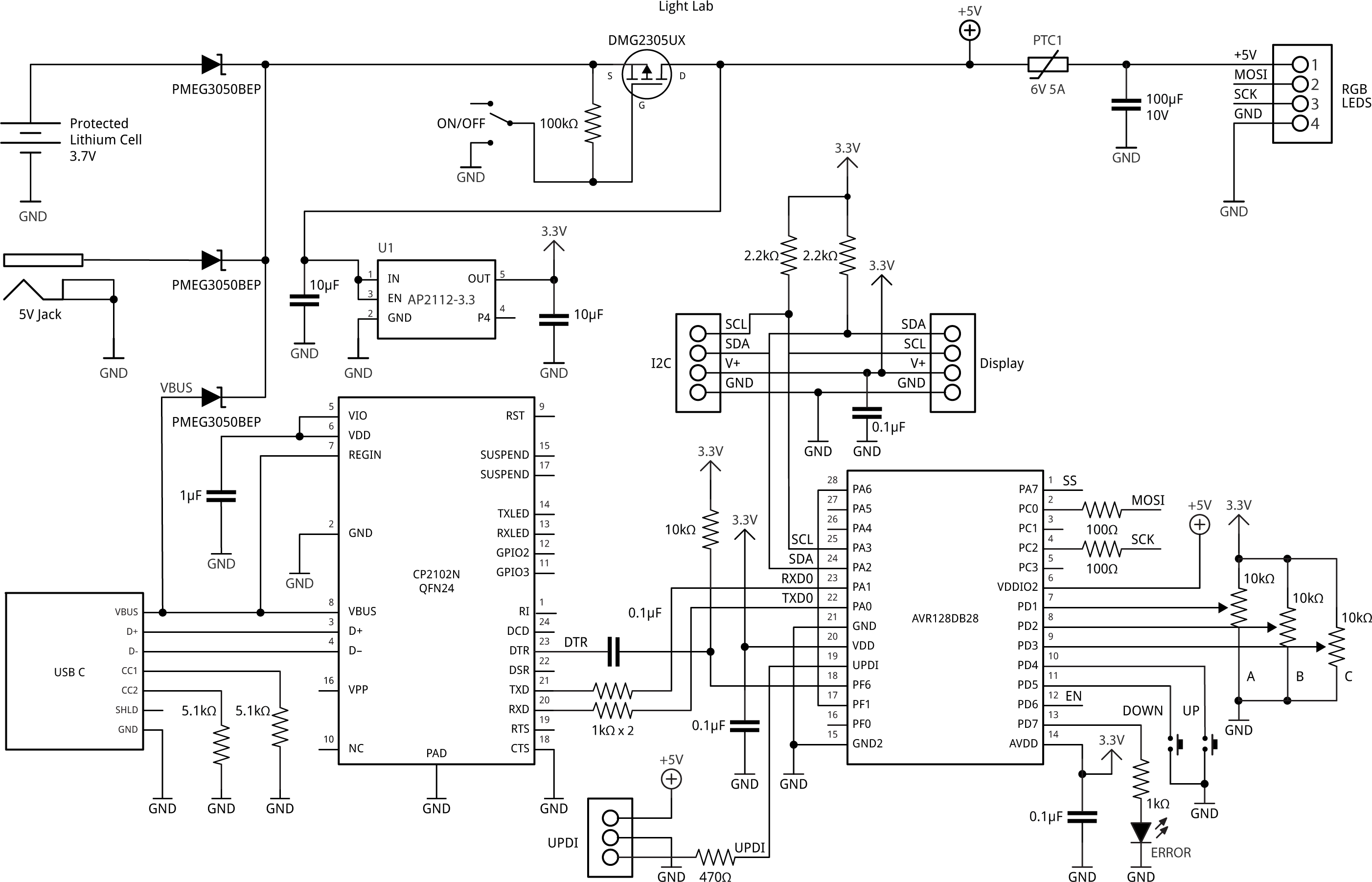
The circuit of Light Lab, a controller that lets you interact with patterns on NeoPixel or DotStar strips.
The microcontroller
Light Lab uses a 28-pin AVR128DB28 microcontroller. It takes advantage of the MVIO (Multi-Voltage I/O) in the DB-series AVR chips to drive the NeoPixel/DotStar outputs with 5V from the USB-C 5V supply rather than the 3.3V powering the chip. This is one of the few times I've found a use for MVIO in a project, but it saves having to use a logic-level converter here.
The current Light Lab program will also comfortably fit on the AVR32DB28 or AVR64DB28, but I chose the largest memory version of the family to allow for future extensions.
The 1kΩ resistors in the TXD0 and RXD0 connections to the microcontroller prevent it from being powered by the outputs from the CP2102N when the USB-C connection is fitted, even when the power is turned off.
The display
I wanted an OLED display that would be wide enough to provide legends for the three potentiometers on the bottom two lines, and found a perfect low-cost 4.24" display on AliExpress, with a resolution of 128x64. It's based on the SSD1309 display controller, which is similar enough to the SSD1306 that I was able to reuse the routines written previously for other projects.
If you have problems locating this display the program should be compatible with the widely available 1.3" 128x64 OLED displays based on the SSD1306 display controller [8], but you'll have to adapt the display connections. The program isn't compatible with SH1106-based displays because they don't support horizontal addressing mode.
Potentiometers
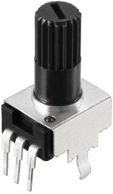
The circuit uses three 9mm series PCB-mounted potentiometers. They should be linear and have a resistance of about 10kΩ; this specification is sometimes marked B103 (B is linear and A is logarithmic), and since these are mounted directly on the PCB the ideal is bushingless, to allow the knob to sit as close to the PCB as possible.
The ones I have recommended in the parts list are from AliExpress, and have a knurled shaft with 18 teeth, suitable for use with fingers or an appropriate knob. Their shaft length is 20mm (measured from the base of the potentiometer, where it sits on the PCB):
Powering options
Because it's difficult to find a compact on/off switch capable of handling 3A I decided to use a P-MOSFET to switch the power; I used the DMG2305 which is rated at 20V, 5A.
If you don't want to use the USB-C input you can omit the USB-C connector and CP2012N USB-to-Serial converter from the board, as well as D1.
If you want to use the USB-C input for power, but don't want to use the Serial upload option, you can omit the CP2012N USB-to-Serial converter.
If you don't want to use the 5V jack input option you can omit the jack socket and D2.
If you don't want the battery option you can omit the battery terminals and D3.
Schottky diodes
Each of the power sources are protected from each other by a Schottky diode, so even if you connect all three at the same time, only one will power the circuit. Most diodes with a rating of 30V and 5A will be suitable. I recommend the PMEG3050BEP, which has a typical voltage drop of 400mV and a reverse current of 90µA, which will give negligible leakage of 5µA from a Lithium cell when Light Lab is switched off. If you're not planning to use a battery I recommend the PMEG3050EP which has a smaller typical voltage drop of 315mV, but a higher typical reverse current of 2.6mA.
PPTC Resettable Fuse
The output to the NeoPixel or DotStar LEDs is protected by a PTC resettable fuse, which will overheat and disconnect the output if the current draw is more than about 3A. The output will be reconnected if the current is reduced.
You can replace this with a 0Ω resistor or wire link if you don't want this protection.
USB to Serial Converter
Light Lab uses a USB-to-Serial converter chip to interface between the USB D+/D- signals and the AVR128DB28 RXD and TXD pins. This allows you to upload programs via the USB-C connection, using a bootloader on the AVR128DB28. It uses the QFN24 version of the Silicon Labs CP2102N USB-to-Serial converter chip, but you could also use the CP2104 which is pin compatible and functionally identical in this circuit.
If you don't want to upload programs via the USB-C connection you can omit the CP2102N USB-to-Serial converter chip, and program the AVR128DB28 using UPDI via the three pins on the back of the board.
ERROR light
The ERROR light is a reverse-mount 1206 LED, but a standard 1206 LED mounted upside-down will work equally well.
The ERROR light flashes if calculating the LED values for the entire strip has taken longer than 20 milliseconds, this being the time for a 50Hz refresh rate. This is to help when designing new patterns, to ensure that there won't be any visible flicker as the LEDs are animated.
Note that the ERROR light may sometimes flicker while you are turning the potentiometers, because of the additional processing needed to calculate the settings, but this can be ignored.
Here's the parts list (click to expand):
► Parts list
Construction
I created a PCB in Eagle, and ordered a set of boards from JLCPCB. I also ordered some plain boards of the same size with just the four mounting holes for use as back panels.
All the surface-mount components are mounted on the bottom of the board:
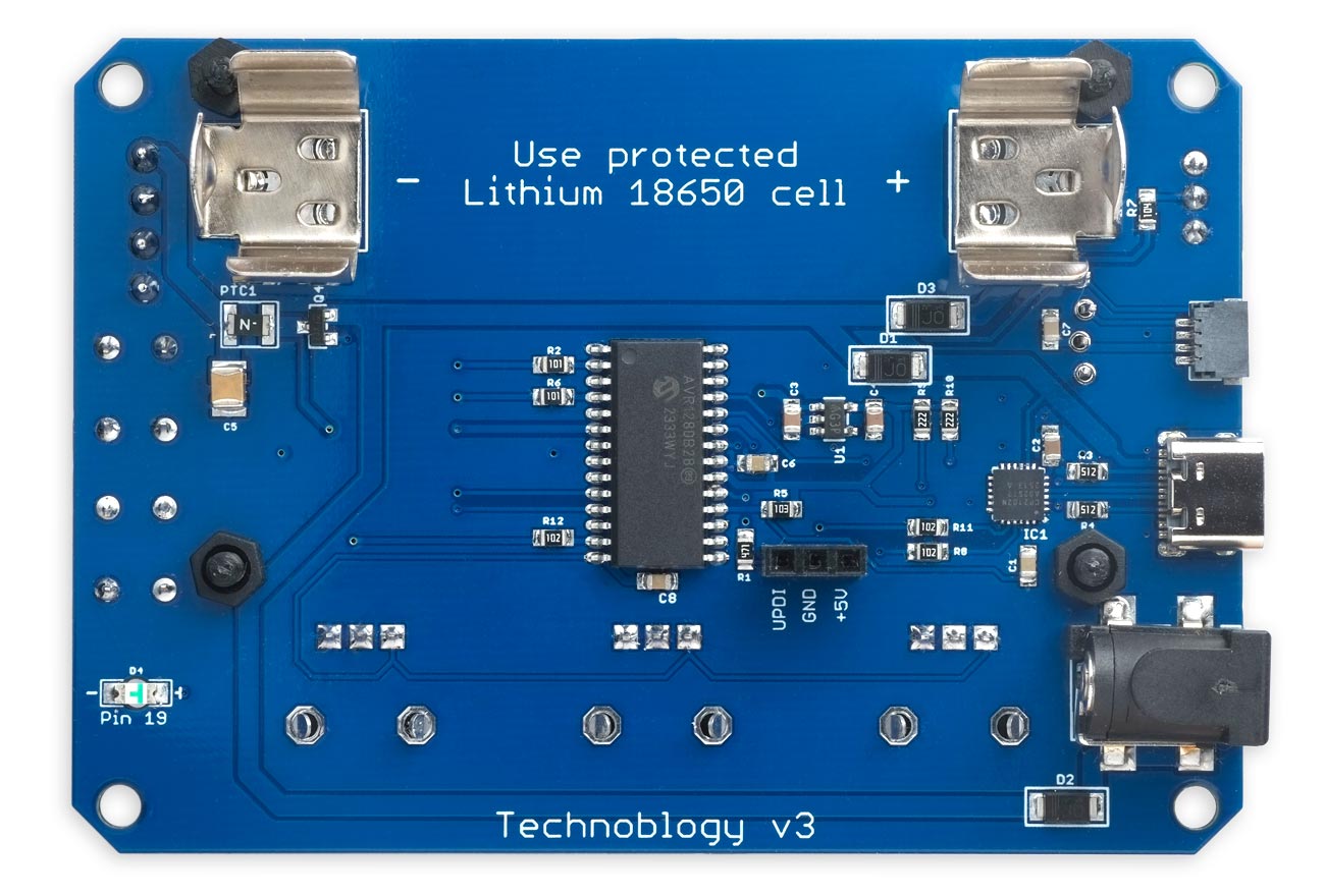
The back of the Light Lab board showing the surface-mount components.
All the resistors, capacitors, and LEDs are 0805 or 1210 size, and the processor chip is a 28-pin SOIC package which is quite easy to solder by hand; the trickiest component to solder is the USB to Serial converter, in a QFN24 package. I used a Miniware MHP50-B5 50x50mm hotplate [9] [10] at 235°C with Chip Quik SMD291AX10T3 solder paste, fitting part of the board at a time on the plate.
After completing the surface-mount components I fitted the potentiometers, push buttons, switch, and connector block to the top of the board with a conventional soldering iron.
Finally, I recommend running solder through the holes in the square pads on the underside of the USB connector to firmly anchor its mounting lugs.
Mounting the display and back panel
The display header pin holes are staggered, with each hole shifted 8 mil (~0.2 mm) off-centre. This allows you to push the display's pin headers in place, and they will stay firmly connected without soldering.
I used four 10mm M3 plastic screws and eight nuts to stand the display above the PCB and hold it into place. Trim the display connector pins so there's no danger of them touching the battery clip.
I give the Eagle and Gerber files for a plain PCB you can use as a back panel; alternatively you could just use a second PCB. I joined this to the main board via M3 screws and 20mm M3 threaded pillars. If you aren't using the battery and battery clips you can use shorter 12mm M3 threaded pillars.
Fitting a battery
You can power Light Lab by fitting a protected 18650 Li-Ion battery to the battery clips on the reverse of the Light Lab board:
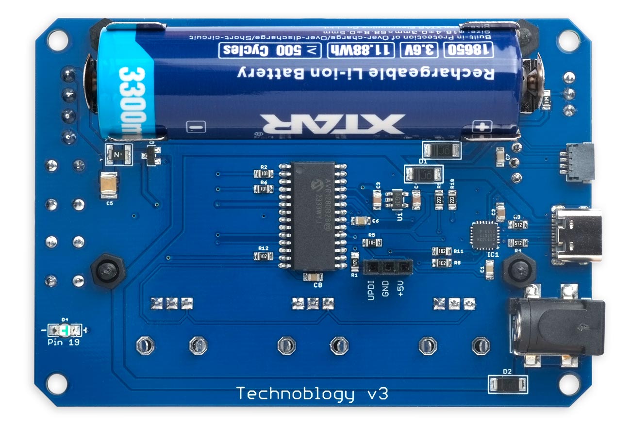
The back of the Light Lab board with a battery fitted.
I used an Xtar 18650 3300mAh 3.6V protected battery [11]. Note that protected cells are actually about 5mm longer than unprotected cells, and the battery clips are spaced to allow for this.
Testing the board
Here's the sequence I use for initially testing boards:
- Apply +5V between VBUS (the anode of D1) and GND (the negative battery terminal) while monitoring the current consumption; it should be about 5mA. Anything well above this indicates a possible short, so disconnect quickly and check for shorts between tracks on the board.
- Connect the USB connector to a computer and check for +5V between the VBUS pin and GND for both orientations of the USB-C connector.
- Check that the USB to Serial chip is providing a serial port in the Arduino IDE Port menu, again for both orientations of the USB-C connector. If no port is available check the solder connections to the USB-C socket, and to the USB to Serial Converter chip.
Next, install a bootloader as described in the following section.
Installing the program
Although you could upload the Light Lab software using the UPDI connector, a better option is to install a bootloader on the AVR128DB28 chip first. This will allow you to subsequently upload programs from the Arduino IDE via the USB-C connector, which is more convenient. It also allows you to use the serial monitor for debugging. I used the serial monitor to print the execution time of each pattern, and to output the screendumps used in this article.
Installing a bootloader
First install Spence Konde's DxCore from GitHub: see DxCore - Installation. I used version 1.5.11.
Then, in the Arduino IDE:
- Choose the AVR DB-series (Optiboot) option under the DxCore heading on the Board menu.
- Check that the subsequent options are set as follows (ignore any other options):
Board: "AVR DB-series (Optiboot)"
Chip: "AVR128DB28"
Clock Speed: "24 MHz internal"
Bootloader Serial Port (…): "USART0 (default pins): TX PA0, RX PA1 …"
You can leave the other options at their defaults, the first option on each submenu.
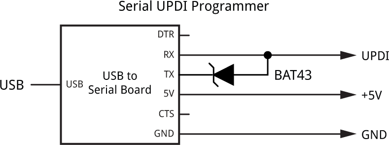
- Connect a UPDI programmer to the three UPDI programming pins on the underside of the board (leave the USB connector on the Light Lab board unconnected).
To program the processor the recommended option is to use a 5V or 3.3V USB to Serial board, such as the SparkFun FTDI Basic board [12], or a USB to Serial cable [13], connected with a Schottky diode as follows. You can substitute a 4.7kΩ resistor for the Schottky diode:
- Set Programmer to the first of the "SerialUPDI - 230400 baud" options.
- Select the USB port corresponding to the USB to Serial board in the Port menu.
- Then choose Burn Bootloader from the Tools menu to upload the bootloader to the AVR128DA32.
Once you've installed a bootloader you can upload the Light Lab software via the serial port by selecting the board from the Port option.
Uploading the program
To upload the Light Lab software from the Arduino IDE:
- Leave the option AVR DB-series (Optiboot) selected under the DxCore heading on the Board menu, and check that the subsequent options are set as before (ignore any other options):
Board: "AVR DB-series (Optiboot)"
Chip: "AVR128DB28"
Clock Speed: "24 MHz internal"
Bootloader Serial Port (…): "USART0 (default pins): TX PA0, RX PA1 …"
This time the Programmer option is irrelevant.
- Connect a USB cable to the USB connector of the Light Lab board.
- Select the board from the Port option. It will be a different port this time.
- Switch on Light Lab to connect power to the AVR128DB28.
- Click Upload to upload the program to the AVR128DB28.
You should then see the Light Lab screen on the display.
How the Light Lab patterns are defined
Fixed-point arithmetic
The Light Lab pattern functions are calculated using fixed-point arithmetic based on a 16-bit word, with 8 bits used for the signed whole-number part of the value, and 8 bits used for the fractional part. This is sometimes called Q8.8.
The format is defined by the typedef:
typedef int16_t Fixed; // Fixed point, 8.8 bits
Working with fixed-point numbers is relatively straightforward provided you remember a few rules:
- You can add and subtract fixed-point numbers as normal.
- To multiply two fixed-point numbers use the function fmul(). You don't need to do this to multiply a fixed-point number by an integer.
- To divide two fixed-point numbers use the function fdiv(). You don't need to do this to divide a fixed-point number by an integer.
Simplified versions of the routines fmul() and fdiv() are as follows:
Fixed fmul (Fixed x, Fixed y) {
  return ((int32_t)x * (int32_t)y) >> 8;
}
Fixed fdiv (Fixed x, Fixed y) {
  return ((int32_t)x << 8) / y;
}
However, Light Lab uses optimised versions of these routines to give faster performance:
In fmul() when the arguments are both 181 or smaller the product will fit in 16 bits, because 181*181=32761, and we can use faster 16-bit arithmetic; otherwise we use 32-bit arithmetic to avoid overflow:
Fixed fmul (Fixed x, Fixed y) {
  if (x>181 || x<-181 || y>181 || y<-181) return ((int32_t)x * (int32_t)y) >> 8;
  else return (x * y) >> 8;
}
In fdiv(), when x is 127 or smaller x<<8 will fit in 16 bits, because 127<<8=32512, so we can use faster 16-bit arithmetic; otherwise we use 32-bit arithmetic to avoid overflow:
Fixed fdiv (Fixed x, Fixed y) {
  if (x>127 || x<-127) return ((int32_t)x << 8) / y;
  else return (x << 8) / y;
}
The program also predefines some useful fixed-point constants:
const Fixed zero      = 0x000;
const Fixed sixth     = 0x02b;
const Fixed quarter   = 0x040;
const Fixed third     = 0x055;
const Fixed half      = 0x080;
const Fixed twothirds = 0x0ab;
const Fixed one       = 0x100;
The constants zero, one etc are used in the following explanations to denote these fixed-point numbers.
Using space-time expressions
The usual approach to displaying patterns on LED strips is to write the colours you want to display into a buffer, and then write the buffer to the strip. If you want to create a dynamic, changing light display you write a program to handle the changes and timing that you want to use.
Light Lab uses a different approach called a space-time expression. This is a single expression that tells you what the value of each RGB channel g is at a particular position x along the strip, at time t. The variable x is a fixed-point value between zero and one, and t is a fixed-point value that increases in seconds from zero.
In addition, the three variables a, b, and c give the settings of the three Logic Lab controls, and return a fixed-point value between zero and one, where one corresponds to 100%.
Space-time expressions allows patterns to be defined very elegantly; in fact most of the patterns in Light Lab are defined in one or two statements.
Here's a simple example:
return one;
This simply returns the fixed-point value one at every point along the strip, and so lights up all the LEDs white at full brightness. A more interesting example is:
return tri(x);
This returns the triangle function tri() applied to the position along the strip, x, which gives a bright peak at the centre of the strip fading towards the edges.
Here's another simple example showing how the controls are used:
return c;
This returns the value of the rightmost control, and lights up all the LEDs white to this brightness value.
Many of the patterns use a function hsv() which takes a fixed point value g, and three fixed-point parameters between zero and one:
hsv(g, h, s, v)
The parameter g is the RGB colour channel, taking the values zero, third, and twothirds, corresponding to the positions of red, green, and blue on the hue spectrum. The remaining parameters specify the values of the hue, saturation, and value to be returned. So a very simple pattern is:
return hsv(g, a, b, c);
which allows you to adjust the hue, saturation, and value with the three controls. In fact this is the definition of the pattern Static HSV Display.
The following simple pattern displays a spectrum at full brightness and saturation along the strip:
return hsv(g, x, one, one);
Finally, here's the definition of the Cylon pattern, that displays a coloured peak oscillating backwards and forwards:
Fixed cylon_pattern (uint8_t n, Fixed g, Fixed t, Fixed x, Fixed a, Fixed b, Fixed c) {
  Fixed x2 = fmul(one - b, tri(fract(t)));
  return hsv(g, c, one, tri(clamp(fdiv(x - x2, b), zero, one)));
}
It uses the tri() function twice; one to make the shape of the peak, and one to define the motion of the peak along the LED strip.
The following section describes how the Light Lab patterns are defined, and explains how to add your own patterns.
The pattern table
The complete set of patterns is defined by a pattern table. First, the total number of patterns is defined by the constant PATTERNS:
const int PATTERNS = 22;
Here's the definition of the first three patterns in the table:
pattern_t Pattern[PATTERNS] = {
  { static_rgb_pattern, "Static RGB Display", "", "Red", "Green", "Blue", false },
  { static_hsv_pattern, "Static HSV Display", "", "Hue", "Satn.", "Value", false },
  { waves_pattern, "Colour Waves", "from one end", "Speed", "Satn.", "Value", true },
  ...
};
Each entry in the Pattern[] table consists of:
{ patfn, title, description, label-a, label-b, label-c, two-way }
where:
- patfn is the pattern function name.
- title is the title of the pattern.
- description is the pattern description (optional).
- label-a, label-b, and label-c are the labels for the three controls.
- two-way is true if the first control goes from -50% to 50% rather than 0% to 100%.
The pattern functions
Each pattern function is defined with the following prototype:
fixed_t patfn (uint8_t n, Fixed g, Fixed t, Fixed x, Fixed a, Fixed b, Fixed c) {
  ...
}
where patfn is the name of the pattern function, and the parameters are as follows:
- n is the number of the RGB LED.
- g is the hue corresponding to each RGB channel: zero, third, or twothirds.
- t is the elapsed time, at a rate determined by the leftmost control.
- x is the position on the LED strip. So with a strip of 10 LEDs the first one corresponds to an x value of 0.05*one and the last one corresponds to an x value of 0.95*one.
- a, b, and c are the values of the controls, going from zero at 0% and one at 100%.
All of the parameters apart from n are fixed-point numbers, and all apart from t are in the range zero to one.
The pattern function for the currently selected pattern is called once for each RGB LED in the strip, and for each of the colour channels: R, G, and B. This is repeated at 20 millisecond intervals; in other words, 50 times a second.
Pattern utilities
Each pattern function can make use of the following utility functions:
Fract
The fract function returns the positive fractional part of a fixed-point number a:
Fixed fract (Fixed a) {
  if (a >= 0) return a & 0xff; else return 0x100 - (a & 0xff);
}
Clamp
The clamp function clamps a value v to the range lo to hi:
Fixed clamp (Fixed v, Fixed lo, Fixed hi) {
  return (v<lo) ? lo : (v>hi) ? hi : v;
}
Circular distance
The d function returns the the shortest distance around a circle between two points on a circle of circumference one. It gives a fixed-point number between zero and half, where m and n are the distance of each point around the circle:
Fixed d (Fixed m, Fixed n) { return abs(fract(m - n + half) - half); }
Triangle wave
The tri function provides a triangle wave shape, period one, extent zero to one:
Fixed tri (Fixed x) { return 2 * abs(half - (fract (half + x))); }
Square
The squ function squares its fixed-point argument:
Fixed squ (Fixed x) { return fmul(x, x); }
HSV
Finally the hsv function returns a value that sets RGB channel g to the hue, saturation, and value specified by its three parameters h, s, and v, each of which should be between zero and one:
Fixed hsv (Fixed g, Fixed h, Fixed s, Fixed v) {
  return fmul(2 * (one - 3 * fmul(d(g, h), s)), v);
}
The program
The Light Lab program consists of the following modules:
Saving the configuration
The configuration of Light Lab is defined by a struct State:
struct {
  uint8_t flag     = 0;       // Check for blank EEPROM
  int     leds     = 20;      // Number of LEDs: 20 to 160
  uint8_t led_type = 0;       // Index in array LEDtype[LEDTYPES]
  bool    neopixel = true;    // Type: false = DotStar, true = NeoPixel
  uint8_t bright   = 0;       // Global brightness: 0 (min) to 4 (max)
  uint8_t pattern  = 1;       // Current pattern
} State;
This specifies the settings for the NeoPixel or DotStar strip, and the currently selected pattern. This structure is saved in EEPROM, and loaded on power-up with the command:
EEPROM.get(0, State);
NeoPixel (WS2812 or WS2812B) driver
The NeoPixel driver is based on my earlier project A NeoPixel Driver using AVR Hardware [2]. This version of the program incorporates the following changes from that design:
- The Timer/Counter TCA0 is moved to its alternative position with the waveform outputs on PF0 and PF1, to free up PA2 and PA3 for use as the I2C SDA and SCL lines to drive the I2C display.
- The LUT1 OUT pin is copied to PC2, to be used as the NeoPixel data output.
- PD6 is used instead of PD4 as the EN pin to connect to the SS input on SPI0.
- PD7 is used instead of PF0 for the error LED.
The reason for using PC2 as the NeoPixel data input is to use SPI1 on PC0, PC1, PC2, and PC3 to make it possible to drive DotStar displays, with PC2 as the SCK output, and PC0 as the output to DI. PC0 might have been more logical for the NeoPixel data output, but it's not available as an event output.
The routines forming the NeoPixel driver are:
- ConfigureNeoPixel() - Configures TCA0, SPI0, CCL LUT1, and event CHANNEL0, CHANNEL1, and CHANNEL2.
- ISR(SPI0_INT_vect) - The SPI0 interrupt service routine.
- StartNeoPixel() - Enables SPI0 and starts outputting the NeoPixel data.
On NeoPixel displays there is no global brightness setting, so reducing the Bright value in Settings reduces the resolution of each channel.
DotStar (APA102 or SK9822) driver
DotStar LEDs use a standard SPI two-wire protocol with clock and data lines, so the DotStar driver can use the SPI peripheral in the AVR128DB28 via the standard SPI library calls. The AVR128DB28 has two SPI peripherals, and the most convenient one to use is SPI1 as it allows the same outputs to be used as the NeoPixel driver.
The routines forming the DotStar driver are:
- ConfigureDotStar() - Configures and enables SPI1.
- StartDotStar() - Sends the start frame.
- EndDotStar() - Sends the end frame.
The DotStar format includes a 4-bit global brightness setting, and this is used to change the overall brightness when you change the Bright value in Settings. This has the advantage that it doesn't reduce the resolution of each channel from the full 8 bits.
I2C OLED display driver
The I2C OLED display is based on the SSD1309 display controller, which is similar enough to the SSD1306 to use the same routines used in earlier projects, such as the Walkie-Textie Wireless Communicator.
The main routines are as follows:
- InitDisplay() - Initialises the display.
- DisplayOn() - Turns the display on or off.
- DisplayArea() - Defines the area of the display to be updated by subsequent write data commands.
- ClearDisplay() - Clears the display to black.
- PlotChar() - Plots a 5x7 pixel character to a specified line and column.
- PlotInt() - Plots an integer in a 4-wide field.
- PlotScrollBar() - Plots a scroll bar on the rightmost edge of the display.
Note that the SSD1309 and SSD1306 support three addressing modes: page addressing mode, horizontal addressing mode, and vertical addressing mode, and it was convenient in this application to use horizontal addressing mode.
The SH1106 display controller used in some 128x64 OLED displays only supports page addressing mode, so the program would need a few modifications to work with it.
Controls
The controls consist of three potentiometers read by three ADC inputs, and two push buttons connected to interrupt inputs.
The potentiometers are read by the routine ReadControls(), which implements hysteresis to avoid jitter in the controls, and updates the display when the control value changes.
The push buttons are configured by the routine ButtonsOn(), and they are handled by the ISR(PORTD_PORT_vect) interrupt service routine. This includes a delay of 255 cycles to avoid contact bounce.
User interface
The user interface is displayed using the following routines:
- Status() - Plots the top line of the display, showing the type of LED, number of LEDs, global brightness, and voltage.
- PrintString() - Displays a text string on the display.
- Title() - Displays the pattern title and description centred on the display.
- Labels() - Displays the three control labels, centred within three fields.
- UpdateDisplay() - Redraws the display for a new pattern.
Settings screen
The routine DoSettings() displays the Settings screen, which allows you to select the type of LEDs, the number, and the global brightness:

After editing the settings DoSettings() uses the Watchdog timer to force a reset, to ensure that the program is initialised for the correct LED type, by executing:
CCP = CCP_IOREG_gc; WDT.CTRLA = PERIOD_8CLK_gc;
Setup and main loop
Finally, Light Lab is configured in setup(), and the main program in loop() repeatedly calls refresh().
The function refresh() checks whether the pattern has been changed, updates the global brightness, and reads the controls. It then evaluates the currently selected pattern function for each LED and RGB channel, and outputs the corresponding data:
  for (uint8_t n=0; n<State.leds; n++) {                    // For every LED
    uint8_t *Out = Buffer.col[n];
    Fixed x = (n * one + half) / State.leds;
    if (State.neopixel) while (BufPtr <= n*3);              // Wait until output
    for (int k=0; k<3; k++) {                               // For each RGB channel
      Fixed g = k * one / 3;                                // RGB channel hue

      Fixed value = Pattern[patno].patfn(n,g,t,x,a,b,c);    // Evaluate the pattern

      Out[rgb[k]] = Gamma[clamp(value, zero, one)]/dim;     // Output the value
    }
    if (!State.neopixel) TransferDotStar(n, bright);        // Output DotStar LED
  }
  if (!State.neopixel) EndDotStar();
Before it is output, the value is clamped to the range zero to one, and transformed by the array Gamma[] to match the eye's brightness response function.
Finally, the refresh() routine waits until 20ms have elapsed, to ensure that the LED display is updated exactly 50 times a second.
Frequently asked questions
Can I use Light Lab with RGBW LED strips?
Yes, but you'll have to make a few changes to the program:
- Change the 3 to 4 in the definitions of col[][] and out[].
- Change the 3 to 4 in ISR(SPI0_INT_vect).
- Add an extra SPI.transfer() call in TransferDotStar().
- Unless you just want to ignore it, decide how to use the W channel.
I haven't tested this, so there may be other changes needed.
Can I use Light Lab to drive more than 160 LEDs?
There are two factors limiting Light Lab to about 160 LEDs:
- The time taken to calculate the patterns; see Timings.
- The current capability of the Light Lab 5V output, which is limited to 3A by the PPTC, the maximum available from standard USB-C outputs. The Schottky diodes and P-MOSFET are rated up to 5A.
You can avoid the limitation of the Light Lab output by bypassing it and powering the +5V of the LED display from an external 5V power supply. Connect the GND of the external supply to the Light Lab GND.
My strip has more than 160 LEDs. Can I use it provided I set the length in Settings to 160 or less?
Yes, in theory, although it's possible that when switching on, the whole strip could briefly light up full brightness and overload the output. The PPTC resettable fuse should protect against this.
How can I write my own patterns? I don't understand the space-time expressions.
I hope to explain this in more detail in a future article.
How does the hsv function work?
I hope to explain this too in a future article.
Can I use Light Lab to drive HUB75 RGB LED matrix displays?
No, it's a totally different protocol.
Resources
Here's the whole Light Lab program: Light Lab Program.
Get the Eagle or Gerber files for the PCB here: https://github.com/technoblogy/light-lab.
Or order boards from OSH Park here: Light Lab and Light Lab Back Panel.
Acknowledgements
Thanks to Chris Jordan for help designing Light Lab and the space-time expressions, and providing feedback on early prototypes.
Update
18th January 2026: Added a note about the display holes being staggered so you can mount the display without soldering.
- ^ 12 NeoPixel Ring on Adafruit.
- ^ 16 NeoPixel Ring on Adafruit.
- ^ 24 NeoPixel Ring on Adafruit.
- ^ 1/4 60 NeoPixel Ring on Adafruit.
- ^ 8x8 WS2812 Matrix on Amazon.co.uk.
- ^ 8x8 NeoPixel Matrix on Adafruit.
- ^ 8x8 DotStar Matrix on Adafruit.
- ^ Monochrome 1.3" 128x64 OLED graphic display on Adafruit.
- ^ MHP50-B5 on Adafruit.
- ^ MHP50-B5 on AliExpress.
- ^ Xtar 18650 3300mAh 3.6V Battery Protected on Ecolux Batteries.
- ^ SparkFun FTDI Basic Breakout - 5V on Sparkfun.
- ^ FTDI Serial TTL-232 USB Cable on Adafruit.
blog comments powered by Disqus
